
Figure 1. Rendering of the Almonte River Viaduct. Source: Arenas y Asociados.
Location: Alcántara Reservoir, Cáceres, Spain
Design engineers: Guillermo Capellán, Héctor Beade, Javier Martínez and Emilio Merino (Arenas y Asociados)
Owner: Administration of Railway Infrastructures (Adif)
Contractor: FCC Construction & Conduril Engineering
Completed: 2016
Main Span: 384 m (1260 feet)
Total length: 996 meters (3270 feet)
Structural system: deck arch bridge
Introduction and Context
The Almonte River Viaduct (Figure 1) is a concrete arch bridge that spans almost a kilometer across the Almonte River at the Alcántara Reservoir in the western region of Cáceres, Spain. The bridge, designed by Spanish Engineering firm Arenas y Asociados, is part of a high-speed rail line proposed to connect the two European capitals of Madrid, Spain and Lisbon, Portugal. Initially proposed in 2007, the Spanish portion of this line, which runs 450 kilometers from Madrid to the Portuguese border, is expected to be complete in 2016, but construction has yet to begin on the Portuguese portion of the line [1]. The European Union (EU) has provided much of the funding for this project, upwards of 500 million Euros for the Spanish portion alone [1]. The EU funding has been crucial for this railway project, as both Spain and Portugal are in the midst of serious economic crises.

Figure 2. Map of Spain showing the location of the viaduct. Source: Google Maps.
Construction on the Almonte River Viaduct began in 2011 and is being managed by Adif, the Administration of Railway Infrastructure, a state-owned company under the Ministry of Public Works and Transportation [3, 4]. Once complete, the bridge will be the largest high-speed railway arch bridge and third largest concrete arch bridge in the world [2]. Figure 3 shows an image of the bridge during its construction.
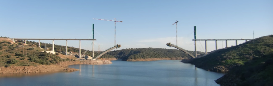
Figure 3. The viaduct under construction in January 2015. Photo: Arenas y Asociados
Design
The Almonte’s final design was the result of a long list of environmental and serviceability constraints. It demanded innovative forms that could meet both the serviceability needs of a high-speed railway bridge and the environmental regulations of the area.
The Almonte River and Alcántara Reservoir are protected areas and the bridge itself is sited adjacent to a reserve (Figure 4). In order to minimize the bridge’s impact on the environment, the engineers were not allowed to place any supports – permanent or temporary – in the river. This specification meant that the bridge would have to span the width of the river, 218 meters [1, 4]. Additionally, the construction process would have to be designed so that all work could be carried out from the land on either side of the river.
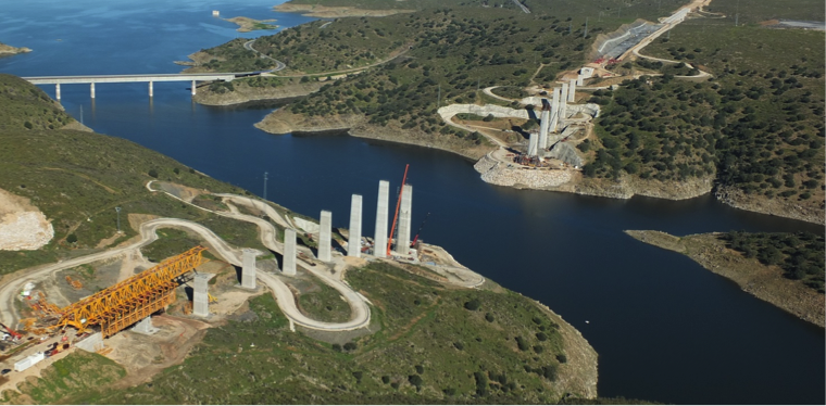
Figure 4. The bridge is located adjacent to a reserve. Source: Arenas y Asociados.
In addition to the environmental regulations, the engineers also had to pay special attention to the dynamic effects on the bridge. Trains crossing the Almonte River Viaduct may reach speeds of up to 350 kilometers per hour and will induce important dynamic effects and braking forces.
The Almonte’s main mechanism for taking the longitudinal forces from trains braking is the fixed point located at the apex of the arch [5]. At the center of the bridge there is a 42 m long fixed point connecting the arch and the deck, shown in Figure 5. Horizontal loads due to the train braking are transferred through the fixed point from the deck to the arch and then into the abutments. All of the horizontal forces present are transmitted to the fixed point, as the columns are connected to the deck with elastomeric bearings, allowing the deck to move longitudinally with respect to the columns [5]. Figure 6 shows how forces caused by trains are transferred to the bridge abutments.
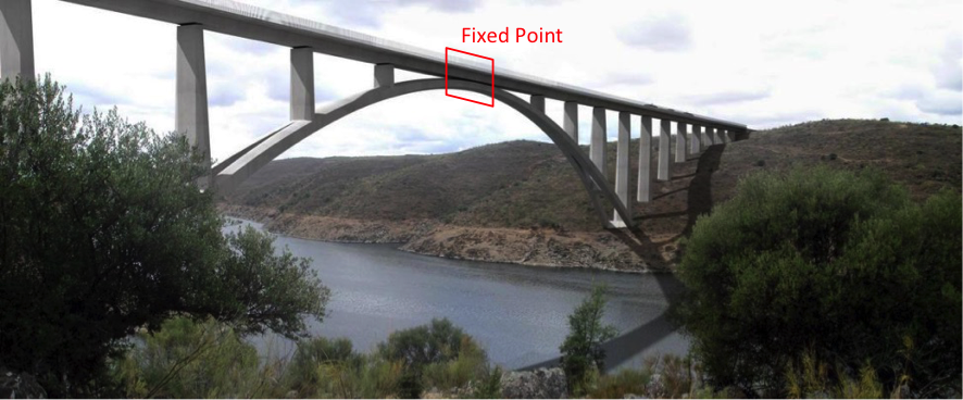
Figure 5. Rendering of the viaduct showing the finished bridge. The fixed point has been marked in red. Image based on rendering by Arenas y Asociados.
Figure 6. A braking train produces a horizontal force equal to mass x acceleration, shown in blue. This horizontal compressive force is transferred through the deck to the fixed point at the top of the arch, and down into the abutments. The red distributed load represents the weight of the train. This vertical force is transferred from the deck, causing bending (1), to the columns in compression (2) and into the abutments (3). Image based on a drawing by Arenas & Asociados.
The simplest design for the supporting piers of this bridge would use a rectangular cross-section with constant width along the height of the column. However, by making two simple adjustments to the conventional pier shape, the designers at Arenas y Asociados were able to lessen the wind effects [2] (Figure 7). First, the cross-section of each column is octagonal, which leads to better airflow around the columns, mitigating lateral wind forces. Additionally, the columns narrow towards the top. This design is efficient because (1) bending moment due to wind is decreased, since the surface area of the column near the deck is decreased, and (2) it results in a higher pier depth in the places where bending moments are higher.
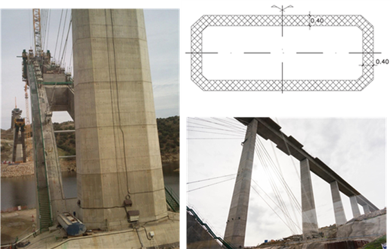
Figure 7. Different views of the piers showing a typical octagonal cross-section and how they are tapered from top to bottom. Photos: M. Chang, drawing: Arenas & Asociados.
Like the columns, the cross-section of the arch varies throughout the structure and takes a hollow octagonal form [2]. The narrow arch width at the crown near the deck is analogous to the narrow pier cross-section near the deck. The arch the section widens towards the abutments, as shown in Figure 8, below. On each half of the arch – 105 meters from the midpoint – the arch splits into two legs, achieving its widest spread of 19 m at the abutments [4]. Instead of maintaining an octagonal shape in each leg, the previously octagonal section is cut into two trapezoidal sections, which, together, form an octagon. The two legs of the arch provide the lateral support necessary to resist wind and other transversal loads acting on the bridge.

Figure 8. Cross sections of the arch represented on a plan view of the arch. The arch changes in cross-section, with its narrowest point at the center of the arch, splitting towards the abutments. Source: Capellán et al. [4].
High-speed rail bridges have stricter serviceability requirements than for roadway bridges: deflections and accelerations must be smaller than those for traditional vehicular bridges. These stricter serviceability demands mean that extra precision was necessary to determine the arch shape. In order to determine the proper shape of the arch, the designers analyzed the forces and stresses in the arch under various loading configurations [2]. Examples of loading cases include a single train over the center of the arch, two trains spaced along the arch, and one train braking at a point on the arch. For each loading condition, the designers determined the resulting pressure line. From these pressure lines the proper axis of the arch was determined so that all pressure lines remain inside the central third of the arch cross section, resulting in an arch that exclusively undergoes compressive stresses [2]. By eliminating tensile stresses in the arch the propensity for cracking is greatly reduced, which leads to a couple of practical benefits. First of all, a crack-free arch encourages long-term durability and reduces required maintenance. Secondly, avoiding cracks gives the arch greater stiffness and limits deformations under load. In other words, by paying closer attention to the shape of the arch, engineers were able to reduce the arch’s cross-section, resulting in both a cheaper and more slender structure [2].
Figure 9. The bridge is designed so that all pressure lines (in blue) remain inside the central third (in red) of the arch cross section. Source: Arenas et al. [2].
Keeping these environmental and technical restrictions in mind, Arenas & Asociados developed an assortment of designs for the Almonte River crossing. Two options were variations of beam bridges, supported by V-shaped legs [4]. By utilizing this shape, the effective span of the bridge is reduced to less than the width of the river. The design team developed this beam option using different materials, such as steel and high strength concrete, and as well as tube and open deck options [4]. The team also explored an option for a cable-stayed bridge, which is often used in spanning large distances and does not require any intermediate supports [4]. For each proposed solution the engineers also had to develop a construction method, keeping in mind all previously described regulations and considerations.
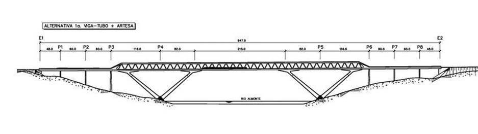
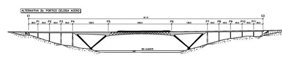
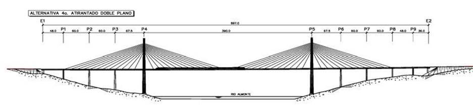
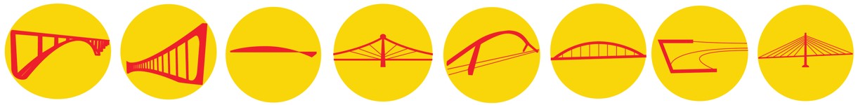
Figure 10. Some of the design alternatives to the arch bridge, from top to bottom: two variations of a V shaped frame with a tube, V shaped frame with a truss, cable stayed. Source: Capellán et al. [4].
Although there were no formal aesthetic requirements for the bridge, the engineers at Arenas & Asociados valued integration into the environment in their design of the Almonte River Viaduct. Ultimately, after considering aesthetics along with all aforementioned criteria, the design team decided to use a single concrete arch to span the river (Figure 11).
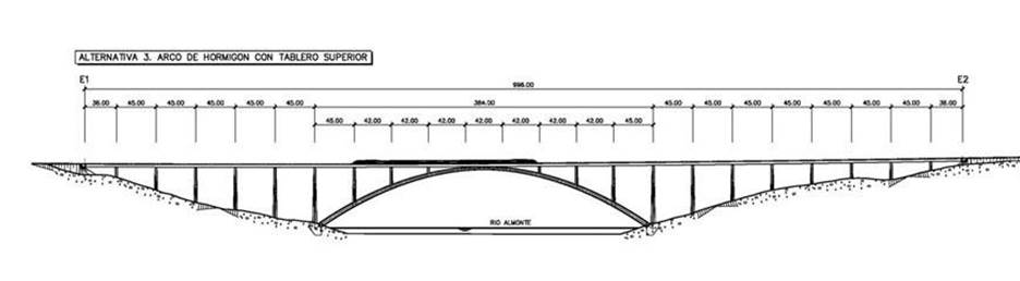
Figure 11. The final arch design for the bridge. Source: Capellán et al. [4].
The Almonte River Viaduct has a main arch span of 384 meters, and a total length of 998 meters. The bridge uses reinforced and prestressed high-strength concrete. The approach spans of the bridge range from 36 to 45 meters, with the distance between columns on the arch reaching 42 meters over the arch [4]. At its apex the arch rises 70 meters above the river.
Construction
A system of movable formwork on the piers was used to construct the deck. Figure 12 shows a snapshot of the construction process for the deck. The pier and spandrel column spacing allows the use of a deck that has a constant depth of 3.1m and width of 14m, allowing for easier construction and minimal long-term maintenance [4]. The arch was constructed using a cantilever method with temporary cables attached to the piers and to temporary steel towers (Figure 13). As previously mentioned, the arch is designed to be exclusively under compressive forces, demanding a cross-section that changes at each point. According to Pablo Cavero of FCC construction, this makes construction “an authentic daily challenge” [5]. Figure 14 shows a sequence of the construction process.
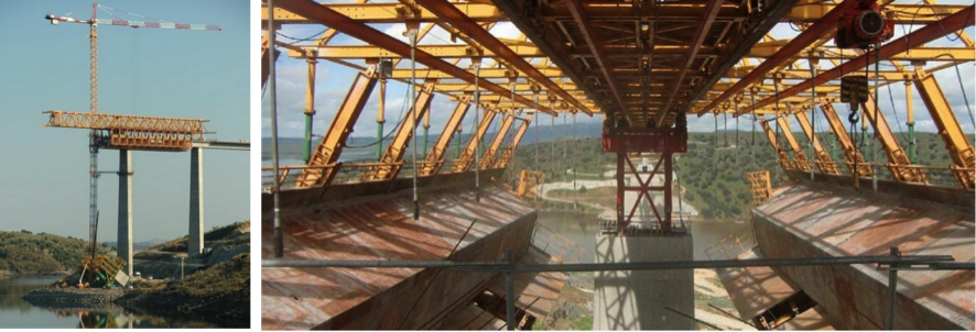
Figure 12. The system of movable formwork used to construct the deck. Source: Arenas & Asociados.
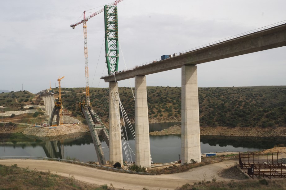
Figure 13. The arch’s cantilever construction implements temporary cable stays. Photo: I. Payá-Zaforteza
Conclusion
The Almonte River Viaduct successfully meets the necessary technical and environmental design constraints in a sophisticated and aesthetically pleasing way. This record-setting bridge plays an integral role in connecting Central and Western Spain via high-speed rail.
Figure 14. Animation of the construction process for the bridge.
References
[1] Administrador de Infraestructuras Ferroviarias (Adif). "High-Speed Lines." www.adif.es. Retrieved on December 4th, 2014.
[2] J.J. Arenas, G. Capellán, H. Beade, E. Merino, J. Martínez, Y. Guil, P. García. “Analysis and Design of the Almonte Bridge." Proc. of the 37th Symposium of the International Association for Bridge and Structural Engineering (IABSE), 2014.
[3] Administrador de Infraestructuras Ferroviarias (Adif). “Learn about Adif." www.adif.es. Retrieved on December 4th, 2014.
[4] G. Capellán Miguel, Héctor Beade Pereda, J.J. Arenas de Pablo, P. García Arias and Ignacio Meana Martínez. “Diseño del Puente Arco de Alta Velocidad Sobre el Río Almonte en el Embalse de Alcántara." Actas del VI Congreso de la Asociación Científico-Técnica del Hormigón Estructural (Ache), Madrid, Spain, 2014. In Spanish.
[5] G. Capellán Miguel. Interview conducted by M. Chang, M. Gerber and J. Wilcots at Princeton University, October 9th, 2014.
[6] P. Cavero. Interview conducted by M. Chang, M. Gerber and J. Wilcots at the Almonte River Viaduct worksite, October 28th, 2014.