
Figure 1: View of the footbridge over the R-3 highway. Photo: Anastase et al. [7].
Design engineer: Leonardo Fernández Troyano (Carlos Fernández Casado, S.L.)
Owner: City of Madrid
Contractor: Teconsa
Built: October 2005 – May 2007
Main span: 110 meters (361 feet)
Total length: 190 meters (623 feet)
Structural system: suspension bridge
Introduction
The footbridge over the R-3 highway in Madrid was completed in 2007 by the engineering firm Carlos Fernandez Casado S.L. The structure is shown in Figure 1 and was designed by Leonardo Fernández Troyano, a Spanish engineer well known for his intuitive and sincere way of rendering forces into form, as well as for his particular sensitivity to aesthetic values. Together with a similar project over the M-40 Motorway, the bridge serves as a connection for pedestrians and cyclists between the districts of San Blas and Vicálvaro.
Economic and Social Context
In the early 2000s, Madrid, along with entire Spain and other countries across Europe, experienced a remarkable economic growth that triggered an “urban-development tsunami” [1]. Fed by the flux of capital created by the economic boom, the city oversaw an intense expansion of its metropolitan area, leading to the need of better infrastructure. Among these urban interventions, a new set of radial highways was completed in 2003 and 2004 to absorb traffic congestion in and out of Madrid, a familiar problem for many large cities. While designed with a practical solution in mind, the highways could also act as barriers, preventing the communication between Madrid’s neighboring districts [2]. Moreover, they caused acoustic and air pollution, contributing to the degradation of the neighborhoods and causing people to call the highways the scars of the city. The necessity for improved walkable connections was evident and several pedestrian bridges were built, among which a set of twin pedestrian suspension bridges, one over the M-40 highway and one over the R-3 highway. These footbridges connect the districts of San Blas and Vicálvaro and provide access to green spaces in the area.
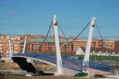
Figure 2: The footbridge over M-40. Source: Fernández Troyano et al. [5].
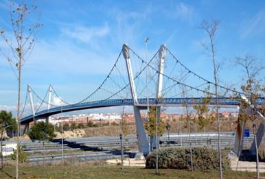
Figure 3: The footbridge over R-3. Source: Fernández Troyano et al. [5].
Given their close relative proximity, it is not surprising that the design of the two bridges over the M-40 and R-3 pays careful consideration to the location of the structures as well as to creating a synchronized ensemble that is aware and respectful of its environment. The two pedestrian bridges thus share the same aesthetic features and similar structural systems.
Although the two bridges are part of the same ontology, factors such as the environment and terrain have generated differences between the two structures. The bridge over the M-40 passes over a motorway that dips below the surrounding terrain, requiring a solution with a single span (see Figure 2 and Figure 4). On the other hand, the bridge over the R-3 crosses a longer distance and is situated at the intersection between R-3 and the M-40 [1], necessitating a multi span structure (see Figure 3 and Figure 4).

Figure 4: The footbridges over M-40 (top) and R-3 (bottom). Source: Fernández Troyano [4].
Sensitive to aesthetics, Leonardo Fernández Troyano designed a slender deck supported by two inclined planes of cables that connect to the sculptural V-shaped towers, representing a gateway from the city into the park (Figure 5). Moreover, the uniquely shaped towers with rounded profiles on the top engender thoughts of symbolic significance, perhaps evoking the sun. On a more light-hearted take, some locals call the two bridges over the M-40 and R-3 the “Chupa Chups Bridges,” as a nod to the lollipop shaped towers (Figure 6).
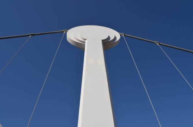
Figure 5: Detail of the sculptural tower. Source: Anastase et al. [7].

Figure 6: The V-shaped towers as seen from the deck. Source: Anastase et al. [7].
Studied Solutions for the Footbridges
Once the boundary conditions for the supports and the length to be provided were established, the engineers considered three potential solutions for the structural system. The options were a cable-stayed bridge, a suspension bridge and a bow string arch bridge, all of which would have been viable for the length of the main span, while allowing for a minimal rise above the highways to avoid excessive sloping [3].
The solution of a bow string arch bridge could have been easily adapted for the M-40, which has a single span, but was an inadequate solution for the R-3, which requires two additional spans of 40 meters, so it was discarded [3]. For a suspension bridge, the towers should have a height of about 0.1 of the span, while for a cable-stayed bridge, the towers’ height should be about 0.2 that of the span. In the end, the suspension bridge was preferred due to the smaller required height of the towers [4]. This option was the most versatile and economical solution, allowing for the necessary clearance, and providing a silhouette for the towers that was neither excessively expensive, nor imposing on the environment.
Structural System of the Footbridge over R-3
With a total length of 190 m (Figure 7 - top) not including the approach ramps, the bridge above the R-3 has a continuous deck made of precast lightweight concrete panels and supported by the hangers, which carry the loads to the main cables. Moreover, the main cables transfer the loads to the towers and the bipod piers. Stiffeners are provided in the deck every 2 m to ensure stability and provide strength [5].

Figure 7: The flow of forces in each component of the suspension bridge due to a uniformly distributed load. Note that tension forces are drawn in blue, and compression forces in red. Source: Anastase et al. [7].
The V shape of the towers is achieved due to the two inclined legs that vary in cross sectional area across the height from 0.85 m2 to 3.75 m2 [4]. They are then topped off with circular drums that support the main cable (figures 5 and 6). The towers are made of steel and filled with concrete and have a total height of 24 m. Inside these drums, a pin support system allows the passing of the main cables through the towers. This system allowed the cables to slide during the bridge’s construction, but once construction was completed, the cables were fixed with clamps [4]. The diameter chosen for the drums suceeds in many respects. The radius is large enough to accommodate the curvature needed to assure structural efficiency of the cable, while in the same time not being disproportionate with the rest of the towers, the cables and the deck.
A key problem with suspension bridges is the lack of stiffness of the main cables that can produce large bending moments and deflections in the deck. This problem can be addressed by including diagonal cable stays, which can be positive – spanning from the top of the towers to the deck, or negative – spanning from the bottom of the towers to the main cables [4]. While positive cable stays are more frequently used, they were inadequate for this project, as they would have made the deck construction harder because a special joint would have been required to connect the cable stays and the deck [5]. By using negative cable stays (Figure 8), the deflections and the bending moments in the deck were controlled, while still keeping the deck thin and the deck construction the simplest. On the other hand, this solution increased the loads in the main cables and required a cable-cable joint connection that was more difficult to design (Figure 9).
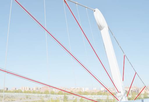
Figure 8: Negative diagonal cable stays. Source: Anastase et al. [7].
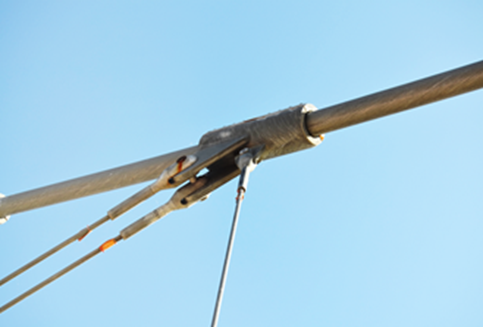
Figure 9: Detail of the connection necessary between the main cable, the hangers and the cable stays. Source: Anastase et al. [7].
Structural analysisCarlos Fernández Casado, Leonardo Troyano’s father, who was also an influential figure in civil engineering in Spain, used to say: “You have to dominate the calculations, so that the calculations don’t dominate you” [6]. Even in a time where structural analysis is governed by computation, it is in the engineers’ beliefs that a sound approach to the process of carrying out a project should not rely only on computer calculations, but should also be able to follow them through simple hand calculations and engineering intuition.
While having quite an intricate structural system, the scientific reasoning behind the design for the footbridge over R-3 can be easily read by looking closely at the structure. A graphic static analysis reveals the efficiency of form that was achieved in the bridge. This method of analysis uses force polygons and basic geometric construction techniques to provide both a qualitative and a quantitative representation of the correlation between the forces and the form (Figure 10).
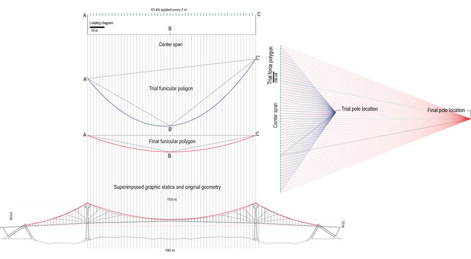
Figure 10: Form finding of the principle main cable’s shape using graphic statics. By superimposing the found shape on the real geometry of the bridge, we observe the accuracy with which they match. Source: Anastase et al. [7].
The bipod piers have their outer leg in tension, while the inner leg is in compression. The towers are mainly in compression, being the bending moments introduced in the towers by the horizontal forces of the cables accounted by an increase in cross sectional area towards the towers foundations (Figure 11).
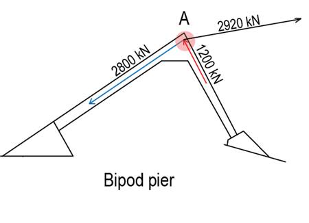
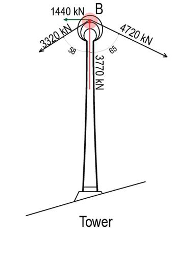

Figure 11: Graphic statics analysis of the forces in the piers and in the towers. The direction and magnitude of the forces is found. Note that tension forces are denoted in blue, while compression forces are in red. Source: Anastase et al. [7].
ConstructionThe construction of the footbridge was done in six main steps (Figure 12). Firstly, the towers and the bipod piers were constructed, taking into account the topography specifications. Next, the main cables were installed, threading them through the towers and securing them into the piers. The third step was connecting the hangers to the main cable and attaching the prefabricated concrete panels of the deck. Each set of hangers (two on each side of the deck), took the weight of one panel. Lastly, the negative diagonal cable stays were installed and then tensioned. Then the joints between the concrete panels were closed by pouring in-situ concrete and the deck was prestressed. After that, pavements, hand-rails and other bridge components were put in place.

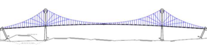
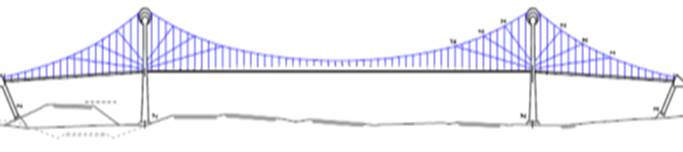
Figure 12: The six steps of the construction sequence of the footbridge over R-3 highway. Source: Fernández-Troyano [4].
The major problem in construction was that the bridge had to be installed with minimum traffic disruption on the highway below [5]. To reach this goal the main cables were installed at night during a traffic interruption. The prefabricated concrete panels and other cable elements – such as the joints and diagonal cable stays were also assembled at night (Figure 13) and required only temporary lane closures [5].
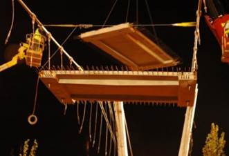
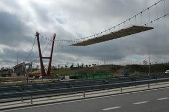
Figure 13: Left – Prefabricated panel of the deck being installed; Right- R-3 footbridge during construction. Source: Fernández Troyano et al. [5].
Concluding Remarks
It becomes evident that the footbridge over R-3 portrays the values of structural art. By being remarkably honest with its structure, considerate of its social context and an aesthetically powerful intervention to Madrid, the bridge represents a successful design. Moreover, the footbridge can be seen as a rendering of Leonardo Fernández Troyano’s creativity and a lesson for future engineers that aspire to design structures with character, in which constrains do not compromise budget or aesthetics, but rather work as catalysts to the engineer’s power to transform ink on paper into functional, unique, and elegant forms in urban or natural environments.
References
[1] F. Jiménez. "Building Boom and Political Corruption in Spain". South European Society and Politics 14: 255-72, 2009.
[2] S. Medialdea. "Dos nuevas pasarelas peatonales sobre la M-40 y la R-3 unen San Blas y Vicálvaro". News published in the newspaper ABC on July 11th, 2007. Retrieved on November 30th 2014. In Spanish.
[3] G. Ayuso. Interview conducted by C. Anastase, J. Azad and D. Buzatu during a site visit to the footbridges over the M-40 and the R-3 Highways. October 26th, 2014.
[4] L. Fernández Troyano. "Proyecto de construcción de dos pasarelas peatonales sobre la M-40 y la R-3", 2005. In Spanish.
[5] L. Fernández Troyano, J. Cuervo Fernandez and G. Ayuso. "Pasarelas sobre la R-3 y la M-40 en los distritos de Vicálvaro y San Blasen Madrid ". Actas del IV Congreso de la Asociación Científico-Técnica del Hormigón Estructural (Ache), Valencia, Spain, 2008. In Spanish.
[6] L. Fernandez Troyano. Interview conducted by C. Anastase, J. Azad and D. Buzatu at Carlos Fernández Casado S.L. October 27th, 2014.
[7] C. Anastase, J. Azad and D. Buzatu. “Footbridge over the R-3 Highway”. Report submitted for the fulfillment of the requirements of the course “CEE 463. A Social and Multi-Dimensional Exploration of Structures”, Princeton University, 2015.