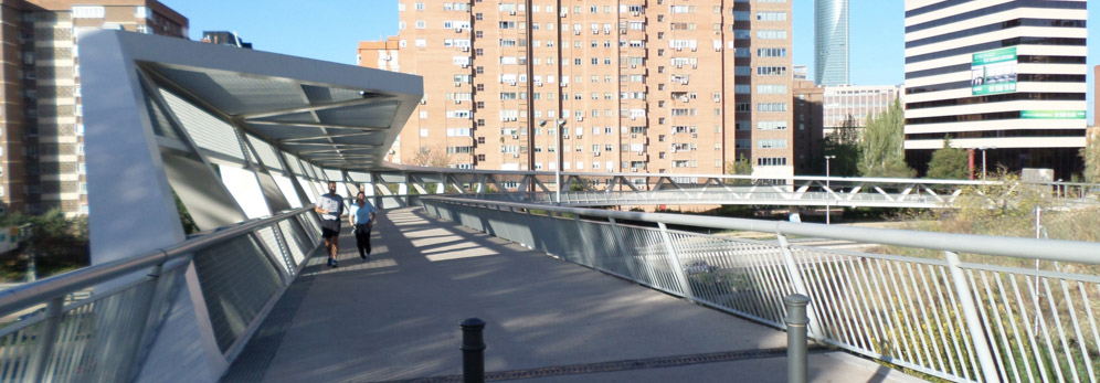
Figure 1: A view of La Paloma footbridge from its east abutment. Photo: Katherine Gao.
Design engineers: Peter Tanner, Juan Luis Bellod, David Sanz (Cesma Ingenieros)
Owner: City of Madrid
Contractor: Intersa
Completed: 2010
Longest span: 52.2 meters (171 feet)
Total length: 191.4 meters (628 feet)
Structural system: truss
Social and Economic Context
During the 1960s, Spain experienced a period of rapid economic growth that has come to be known as the Spanish economic miracle [1]. As Spain’s capital, Madrid was no exception, and a large migration of people from the rural regions surrounding Madrid into the city soon followed. This massive inflow of workers was matched by a steady increase in automobile traffic throughout the city.
Due to industrialization and the need to improve vehicle movement, the M-30, a massive multi-lane highway, was constructed to serve as the innermost ring around the central districts (Figure 2). While the highway provided drivers with an alternative to city streets, it became a barrier to pedestrians attempting to reach the urban center.
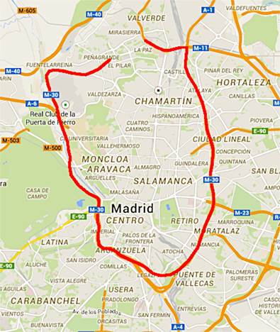
Figure 2: Map of the M-30 highway around Madrid. Source: Google Maps.
To address this issue, portions of the M-30 were redirected underground as part of the 2008 Madrid Río Project, but the eastern portion, which was not underground, remained an obstacle. In light of this, the municipal government called for the construction of seven footbridges over the eastern section of the M-30. La Paloma Footbridge (Figure 1) was the last of these bridges to be completed in this effort to unite the neighborhoods of Madrid and restore pedestrian connections [2].
The Form
La Paloma Footbridge was designed by Peter Tanner, Juan Luis Bellod, and David Sanz of Cesma Ingenieros. The bridge has a total length of 191.4 meters distributed over 4 spans and consists of steel truss members and a composite concrete and steel slab [3]. In choosing a form for this bridge, the engineers had to take into account many site constraints. Connecting the districts of Chamartin and Ciudad Lineal, the bridge needed to meet an 8 meter rise in elevation, maintain a 6 meter clearance above the 75 meter-wide highway, and accommodate accessibility with a gentle 4% slope [3]. To achieve this, the engineers at Cesma decided to use a curved structure as seen in Figure 3. Forming about a quarter of a circular arc, the curve elongates the bridge and allows for a less steep change in elevation from one side to the other.
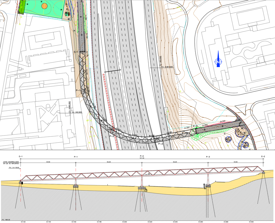
Figure 3: Plan (top) and Elevation (bottom) of La Paloma. Source: Tanner et al. [3].
The shaping of the cross-section and the piers is another unique feature of La Paloma Footbridge (Figure 4). Shaped as a C, the cross-section is composed of three steel trusses − one in the top flange, one in the bottom flange, and one in the web. These truss members are made of welded trapezoidal box sections whose cross-sectional dimensions vary in the web and bottom flange diagonals. The piers are Y-shaped and slanted at the same angle as the web. Their upper branches are integrated into the web as they form two of the web’s diagonal truss members [3].
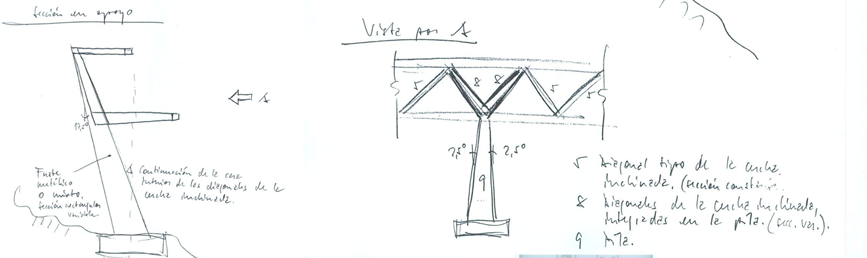
Figure 4: Initial sketches of the cross-section and pier geometries. Courtesy of P. Tanner.
Structural Analysis
Having chosen a curved bridge design for La Paloma, the engineers at Cesma needed to pay special attention to torsion, which develops based on three responses: (1) curvature in between supports; (2) the center of twist not corresponding to the center of gravity; and (3) bending forces on a curved section.
The first torsional response refers to the center of gravity of the curved structure not falling on the line connecting the supports of the bridge. This eccentricity results in an overturning motion of the bridge towards the outside of the curve as visualized in figures 5 and 6.
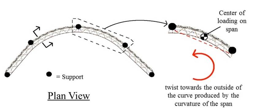
Figure 5. Torsional response due to the curvature between supports. Adapted from Bellod and Tanner [5] by J. Stearns.
Figure 6: An illustration of the direction of torsion (towards the outside of the curve) due to the bridge's curved nature. Image by E. Shullman.
The second torsional response is related to the asymmetry of the cross-section: the shear center does not coincide with the center of gravity (Figure 7). Shear center refers to the location where a load can be applied without causing the section to twist and in the case of C-shape sections, the shear center lies outside of the C. On the other hand, the center of gravity sits inside the C and this eccentricity results in the twisting of the bridge towards the inside of the curve. This acts opposite to the rotation due to the overall curvature of the structure and is illustrated in figures 7 and 8.
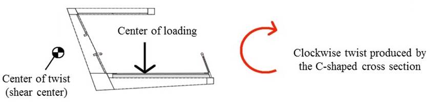
Figure 7: Shear center in relation to the center of gravity for the C-shape section. Adapted from Bellod and Tanner [3] by J. Stearns.
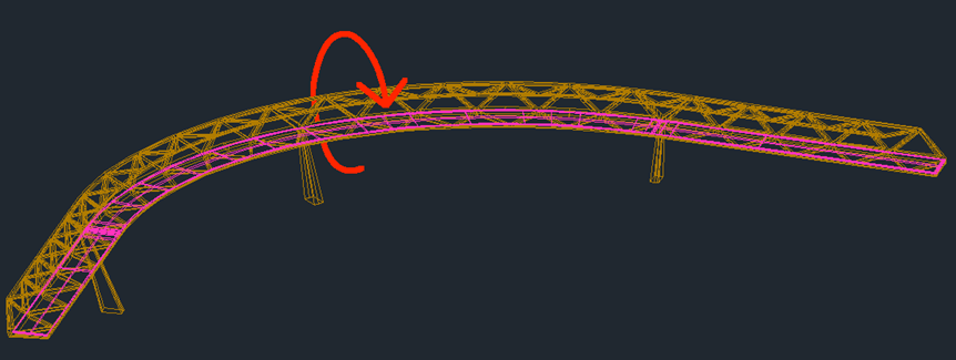
Figure 8: An illustration of the direction of torsion (towards the inside of the curve) due to the shear center being outside of the web. Image by E. Shullman.
Finally, the third torsional response relates to the effect of bending forces on a curved section. La Paloma Footbridge is a continuous four-span bridge therefore it experiences negative bending in the interior supports (piers), meaning tension in the top flange and compression in the bottom flange. Because the bridge is curved, these negative bending moments generate deviation forces perpendicular to the bridge axis at the interior supports. These deviation forces point towards the inside of the curve in the top flange and towards the outside of the curve in the bottom flange and provoke the reactions in the piers shown in Figure 9. These horizontal reactions produce a rotation towards the inside of the curve (refer once again to Figure 8) [3].
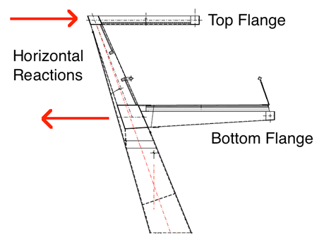
Figure 9: The horizontal reactions in the flanges that are a result of the negative bending at the piers and the curvature of the bridge. Source: Adapted from Bellod and Tanner [5] by J. Stearns.
The supports (piers) must resist uncompensated torsional moments produced by the three torsional responses as well as bending moments transferred by the deck. To achieve this, the design of the piers has increasing cross-sectional dimensions in the direction of the foundations [3].
Construction
The constraints of the project not only presented challenges with the design of La Paloma, but with the construction process as well. The highway was to remain open during construction, which resulted in the bridge being constructed in modular sections near the site and then transported and assembled during nighttime hours.
First, the foundations and abutments were built and the shafts of the Y-shape piers were installed. Each of the four individual spans was then hoisted into position and placed on temporary support towers. These provisional supports were utilized in order to adjust the exact orientation of the pier shafts and ensure a smooth connection between the piers and the spans as seen in Figure 10. Once all adjustments were complete, the pier shafts were welded to the truss spans and the temporary towers were removed. Overall, the construction and assembly process was very efficient and helped to minimize traffic disruption as well as the cost of the project, which was about 3 million euros [3].
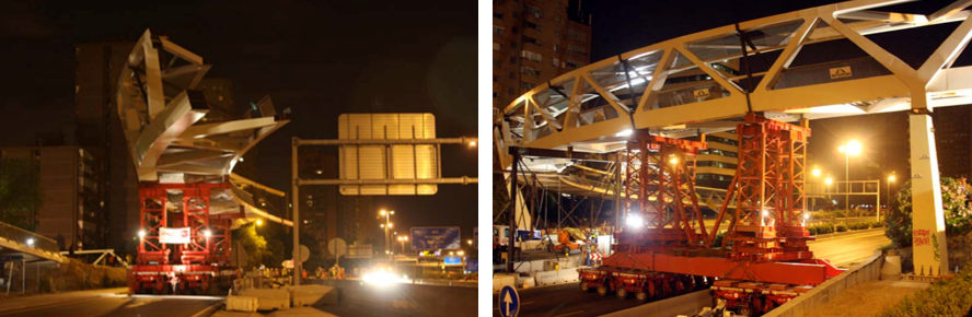
Figure 10: Photos of the construction process: transportation of one of the four spans to the site (left) and the positioning of the final span before welding (right). Source: ALE Heavylift.
Conclusion
La Paloma Footbridge was the last of seven pedestrian bridges built in an effort to unite districts separated by the M-30 highway and restore pedestrian connections. Designed by the engineers at Cesma Ingenieros, La Paloma Footbridge embodies the firm’s core values. Cesma Ingenieros is dedicated to designing innovative structures that satisfy “functional, geometric, constructive, and economic conditions” [4]. This ideology is evident in La Paloma and this bridge serves as an excellent example of how demanding design specifications and constraints, rather than hinder creativity, can instead bring about the creation of truly remarkable structures.
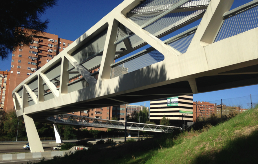
Figure 11: A view of La Pasarela de La Paloma from the below the deck. Photo: J. Stearns.
References
[1] Article “Spain.” In Encyclopædia Britannica. http://www.britannica.com. Retrieved on November 20th, 2014.
[2] Ayuntamiento de Madrid. “Pasarela de La Paloma, la séptima en el arco Este de la M-30.” In http://www.madrid.es . Retrieved on October 4th, 2014. In Spanish.
[3] P. Tanner, J.L. Bellod and D. Sanz. “Paloma Footbridge, Madrid, Spain.” Structural Engineering International, 21 (4): 497-502, 2011.
[4] Cesma. Company Presentation. In http://www.cesmaingenieros.com. Retrieved on October 4th, 2014.
[5] J.L. Bellod and P. Tanner. "Proyecto modificado nº1 del proyecto de mejora de la permeabilidad transversal en el arco este de la M-30, entre el nudo de La Paloma y el enlace de Costa Rica, pasarela en el Nudo de la Paloma." 2009. In Spanish.